Dr. Vadym Zayets
v.zayets(at)gmail.com
My Research and Inventions
click here to see all content |

Dr. Vadym Zayetsv.zayets(at)gmail.com |
|
|
classic model ofspin transportmodel of spin-down/spin-up bandsmore chapters on this topic:IntroductionBasic Transport equationsSpin and charge currentsSpin drainNon-magnetic metalsFerromagnetic metalsSemiconductors (Basic)Threshold spin currentSpin gain/dampingSpin RelaxationSpin Hall/ Inverse Spin Hall effectsee-interaction
classic model ofspin transportmodel of spin-down/spin-up bandsmore chapters on this topic:IntroductionBasic Transport equationsSpin and charge currentsSpin drainNon-magnetic metalsFerromagnetic metalsSemiconductors (Basic)Threshold spin currentSpin gain/dampingSpin RelaxationSpin Hall/ Inverse Spin Hall effectsee-interaction
classic model ofspin transportmodel of spin-down/spin-up bandsmore chapters on this topic:IntroductionBasic Transport equationsSpin and charge currentsSpin drainNon-magnetic metalsFerromagnetic metalsSemiconductors (Basic)Threshold spin currentSpin gain/dampingSpin RelaxationSpin Hall/ Inverse Spin Hall effectsee-interaction
classic model ofspin transportmodel of spin-down/spin-up bandsmore chapters on this topic:IntroductionBasic Transport equationsSpin and charge currentsSpin drainNon-magnetic metalsFerromagnetic metalsSemiconductors (Basic)Threshold spin currentSpin gain/dampingSpin RelaxationSpin Hall/ Inverse Spin Hall effectsee-interaction
classic model ofspin transportmodel of spin-down/spin-up bandsmore chapters on this topic:IntroductionBasic Transport equationsSpin and charge currentsSpin drainNon-magnetic metalsFerromagnetic metalsSemiconductors (Basic)Threshold spin currentSpin gain/dampingSpin RelaxationSpin Hall/ Inverse Spin Hall effectsee-interaction
classic model ofspin transportmodel of spin-down/spin-up bandsmore chapters on this topic:IntroductionBasic Transport equationsSpin and charge currentsSpin drainNon-magnetic metalsFerromagnetic metalsSemiconductors (Basic)Threshold spin currentSpin gain/dampingSpin RelaxationSpin Hall/ Inverse Spin Hall effectsee-interaction |
Spin Drain
Spin and Charge Transport. Classical model of the spin-up/spin-down band.
|
 |
Fig.1 The charge current flows between the charge source and the charge drain |
 |
| Fig.2 The spin current is generated at the spin source and freely flows in all directions |
Even though, spin and a charge are undivided features of an electron, there is a significant difference between flows of charge and spin in a solid. In contrast to the charge current, which always flows from a source to a drain, a flow of the spin current does not require a drain. After been emitted from a source, the spin current propagates in material until it decays.
The movement of a charge is influence by both the electron diffusion towards a smaller electron concentration and the electron diffusion along an electrical field. In contrast, the movement of spin is only influenced by the diffusion towards a smaller spin concentration.
Both a charge source and a charge drain are necessary in order for the charge current to flow. The charge is drifted by the electrical field from the charge source towards the charge drain. In the absence of a charge drain the charge current does not flow. For example, in the imaginary case when there is no charge drain, but there is a charge flow, the charge will be accumulated at some point. The accumulated charge will induce a long-range electrical field, which is in the opposite direction to the charge current. Therefore, the charge flow will stop.
In contrast, only a spin source is necessary for the spin current to flow. The flow of the spin current does not require a spin drain. A spin accumulation does not induce any sufficiently-strong long-range field, which may stop spin diffusion. As a spin accumulation created at the spin source, it diffuses form regions of larger spin concentration towards the regions of smaller spin concentration.
 |
Fig.2 The flows of spin and charge currents |
Even though, the flow of spin does not require a spin drain, the spin drain plays an important role in spin transport. Any conductive material, in which the spin current rapidly decays, may be considered as a spin drain. The smaller conductivity and the longer spin diffusion length of the material of the spin drain, the stronger the influence on the spin transport the spin drain has. The following examples demonstrate the cases when a spin drain has a substantial influence on spin transport.
All structures consist of a metallic wire and a spin drain. The materials of the wire and the drain are non-magnetic metals. The obtained results are valid also in the case of ferromagnetic metals and semiconductors, but the effective length (semi) or (FM) should be used instead of the intrinsic spin diffusion length. The solution was calculated by solving the Gerber-Fert diffusion equation by the Finite Element Method. The conductivity and out of plane thickness of the wires were 3.774e7 S/m and 1 um, respectively. The spin drain is a metallic wire with larger conductivity. The spin drain effectively attracts spin current only when its conductivity is significantly larger than the conductivity of other wires in the structure. In order to clarify the influence of the spin drain, the spin diffusion was compared between the case, when the drain conductivity is smaller and the influence of the spin drain is not significant, and the case, when the drain conductivity is larger and the influence of the spin drain is significant.
This example demonstrates the reduction of the spin current due to the presence of a spin drain.
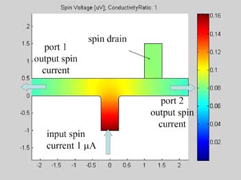
Figure 2 shows the geometry of a T-splitter. It consists of a metallic wire, which splits the input spin current into two directions. For the output ports 1 and 2, the open boundary conditions were applied and spin current flows out of these ports. Near output port 2 there is a spin drain, which is a metal with conductivity different from that of metal of T-splitter. The spin drain contacts the T-splitter, but its other boundaries are isolated. The spin diffusion length of both the T-splitter and the spin drain is 5 um.
Figure 3 shows the calculated output spin currents at Ports 1 and 2 as a function of the ratio of the conductivity of the spin drain to the conductivity of the wire of the T-splitter. In the case when the conductivity of the spin drain is small, the influence of the spin drain on the spin transport is weak and the spin current is split almost equally between ports 1 and 2. As the conductivity of the spin drain decreases, more spin current decays inside the spin drain and the output spin current from ports 1 and 2 rapidly decreases. Since port 2 is closer to the spin drain, the reduction of the spin current at this port is more rapid. However, the influence of the spin drain on the spin current in Port 1 is still significant despite the long distance between port 1 and the spin drain.
 |
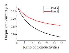 |
Fig.2 The spin chemical potential in T splitter. The T-splitter is made of a conductive metal . The spin drain is connected to the right arm of the T-splitter,. The spin drain is a conductive wire made of another metal. The sizes in um. |
Fig.3. Output spin currents at Ports 1 and 2 as a the function of the ratio of metal conductivity of the spin drain and T-splitters |
Figure 3 shows the calculated output spin currents at Ports 1 and 2 as the function of the ratio of the conductivity of the spin drain to the conductivity of the wire of T-splitter. In the case when the conductivity of the spin drain is small, the influence of the spin drain on the spin transport is weak and the spin current is split almost equally between ports 1 and 2. As the conductivity of the spin drain decreases, more spin decays inside the spin drain and the output spin current from ports 1 and 2 rapidly decreases. Since port 2 is closer to the spin drain, the reduction of the spin current at this port is more rapid. However, the influence of the spin drain on the spin current at Port 1 is still significant despite the long distance between port 1 and the spin drain.
Figures 4 and 5 are animated pictures, which show how the distribution of the spin chemical potential and the spin current are modified when the conductivity of the spin drain increases. In the case when the conductivity of the spin drain is the same as that of the wires of the T-splitter, the spin drain has little influence on the spin transport and almost equal amounts of spin current split between the two ports. In the case when the conductivity of the spin drain is 20 times larger than the conductivity of the wires of the T-splitter, the spin current is mostly directed into the spin drain, because the spin drain attracts the spin current.
 |
 |
Fig.4 Animated picture. Spin chemical potential in T-splitter. Animated parameter is a ratio of conductivity of spin drain to conductivity of metal wire. |
Fig.5 Animated picture. Magnitude of spin current in T-splitter. Animated parameter is a ratio of conductivity of spin drain to conductivity of metal wire |
This example demonstrates the influence of the spin drain on the effective spin diffusion length in a metallic wire. It demonstrates that there is a reduction of the effective spin diffusion length in vicinity of a spin drain.
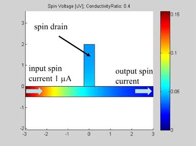
Figure 6 shows the geometry of the metallic wire with a spin drain. It consists of a metallic wire, in the middle of which the spin drain is connected. A spin drain is a metal with conductivity different from that of metal of the wire. The input of the spin current is at left side of the wire. For the right side of the wire, open boundary conditions were applied and spin current flows out of this port. The spin drain contacts the wire, but its other boundaries are isolated. The spin diffusion length of both the wire and the spin drain is 3 um.
Figures 6,6a and 7 are animated pictures, which show how the distribution of the spin chemical potential ![]() and the spin current are modified when the conductivity of the spin drain increases. In the case when the conductivity of the spin drain is smaller than the conductivity of the wire, the spin current mainly flows in the wire and only a little of the current enters the spin drain. In the case when the conductivity of the spin drain is larger than the conductivity of the wire , all spin current flows into the spin drain and only a little of the spin current proceeds to flow into the right-side of the wire.
and the spin current are modified when the conductivity of the spin drain increases. In the case when the conductivity of the spin drain is smaller than the conductivity of the wire, the spin current mainly flows in the wire and only a little of the current enters the spin drain. In the case when the conductivity of the spin drain is larger than the conductivity of the wire , all spin current flows into the spin drain and only a little of the spin current proceeds to flow into the right-side of the wire.
 |
 |
Fig.6 Spin chemical potential |
Fig.6a Animated picture. Spin chemical potential |
 |
Fig.7 Animated picture. The spin current in wire with spin drain. Animated parameter is a ratio of conductivity of spin drain to conductivity of metal wire |
Figures 8 and 9 show the spin chemical potential ![]() and the spin current in the middle of the wire. The figures are animated to show the variation of the distribution for the spin chemical potential and the spin current when conductivity of the spin drain increases. For comparison, the green line shows the spin chemical potential and the spin current in the case when there is no spin drain. In both figures the scale of the y-axis is logarithmic.
and the spin current in the middle of the wire. The figures are animated to show the variation of the distribution for the spin chemical potential and the spin current when conductivity of the spin drain increases. For comparison, the green line shows the spin chemical potential and the spin current in the case when there is no spin drain. In both figures the scale of the y-axis is logarithmic.
In the case when there is no spin drain, the plots of both spin chemical potential and spin current are straight lines. The spin chemical potential and spin current decrease e-times each distance equal to the spin diffusion length. In the presence of the spin drain they are not linear. When the spin current has passed the spin drain, the spin drain does not affect the spin diffusion and the decay slope of the spin current is the same as in the case without the spin drain. However, before the spin drain the decay of the spin current is slower than in the case without the spin drain. That means the effective spin diffusion length becomes longer due to the spin drain. Since the spin current is attracted by spin drain, spin diffusion is faster and as result the spin current dissipates over a longer distance. This is a reason for the shortening of the spin diffusion length in the presence of a spin drain.
The "spin drain" effect should be considered during the measurements of the spin diffusion length by a non-local technique.
 |
 |
Fig.8 Animated picture. The spin chemical potential |
Fig.9 Animated picture. The spin current in the middle of the wire. Animated parameter is a ratio of conductivity of spin drain to conductivity of metal wire |
The spin drain is just a metallic wire having a sufficiently high conductivity and a sufficiently short spin diffusion length, meaning, that any conductive wire may be considered as a spin drain. This implies that the shape of the wire might affect spin diffusion.
This example demonstrates the influence of the shape of a metallic wire on the effective spin diffusion length.
 |
 |
 |
Fig.10 The spin chemical potential in wire with variable width. . Animated parameter is a ratio of width of output wire to width of input wire. |
Fig.11 The spin current in wire with variable width. Animated parameter is a ratio of width of output wire to width of input wire. | Fig. 12 Magnitude of spin current along wire with variable width for different width ratios between input to output. Black line represents the case of a straight wire. |
The spin transport was calculated in the structure, which consists of two connected wires. The widths of the wires are different. The input of the spin current is at left side of the wire. For the right side of the wire, open boundary conditions were applied and the spin current flows out of this port. The spin diffusion length in both wires is 3 um.
Figures 10 and 11 are animated pictures, which show how the distribution of the spin chemical potential and the spin current are modified when the width of the output wire is varied.
Figure 12 shows the magnitude of the spin current for different ratios of the width of the input to output wires. The spin current was calculated by integrating the spin current density over the wire cross-section. Because of the variable width, the distribution along the wire is different for the spin current and for the spin current density.
As in example 2, when a spin drain attracts spin current, the spin relaxation becomes slower. As can be seen from Fig.12, the spin relaxation in the input wire becomes slower in the case of a wider output wire (blue and magenta lines) and the spin relaxation becomes faster in the case of a narrower output wire (green and red lines). Therefore, the wire of wider width could be considered as an effective spin drain.
 |
 |
 |
Fig.13 The spin chemical potential |
Fig.14 The spin current. Animated parameter is a ratio of width of output wire to width of input wire. Green line represents the case of a straight wire. | Fig.15 The spin current. Logarithmic scale.Animated parameter is a ratio of width of output wire to width of input wire. Green line represents the case of a straight wire. |
Figures 13-15 show the spin chemical potential and the spin current in the middle of the wire. The figures are animated to show the variation of the distribution for the spin chemical potential and the spin current when the width of output wires is varied. For comparison, the green line shows the spin chemical potential and the spin current in the case when the widths of the input and output wires are equal.
The broadening and narrowing the volume of wire along the diffusion of the spin current modifies the effective spin diffusion length.
 |
Fig.16 The spin current in wire with variable width. Animated parameter is a ratio of width of output wire to width of input wire. |
I will try to answer your questions as soon as possible

 It is important!!!! All data on this page are calculated based on the model of the spin-up/spin-down bands. The model of the spin-up/spin-down bands ignores
  For the modified model, which includes all above-mentioned facts,